METHOD STATEMENT FOR INTEGRITY (OR DOOR FAN) TESTING ENCLOSURES PROTECTED BY GASEOUS FIRE EXTINGUISHING SYSTEMS
1. Background
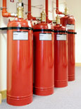
Successful extinguishant of a fire by a gaseous extinguishing system is critically dependent upon the extinguishing concentration being maintained for a specified period after discharge. A retention time of ten minutes applies in most cases. Failure to do so may result in reignition and fire spread.
Integrity testing using door fan methodology provides a means of predicting the retention time without the need to release the extinguishing gas. It is a requirement of all relevant British, European and International Standards that integrity tests be conducted on initial installation and thereafter at annual intervals.
2. Methodology
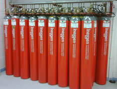
The test methodology is in accordance with the general requirements specified in the relevant parts of BS 5306, BS:ISO 14520, NFPA 12A, NFPA 2001 and the BFPSA Code of Practice for Gaseous Extinguishing Systems. It is applicable to all extinguishing gases (e.g. halon1301, FM200, argonite) and can be used for descending interface, mechanical mixing and extended discharge applications.
3. Principle
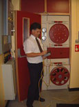
The door fan equipment is located in a doorway to create small pressure differentials between the enclosure and surrounding areas. Pressure and airflow measurements are made, from which the leakage characteristics of the enclosure are established. The predicted retention time is calculated from these leakage characteristics and the enclosure and extinguishing system data.
4. Apparatus
Calibrated 240V/110V AC variable speed fan(s), frame which fits into door opening, pressure gauges, chemical smoke pencils, portable computer and sundries.
5. Procedure
The enclosure is measured, a sketch plan made and the type and quantity of extinguishant recorded. The height of the highest hazard in the enclosure (risk height) is noted.
Where relevant, doors within the enclosure are opened and a number of false floor and ceiling tiles are removed so that the protected enclosure is tested as one space. False ceiling tiles are not removed where the ceiling void is not protected. A return air path is established outside the enclosure by opening doors/windows as appropriate.
The door fan equipment is set up in a suitable door opening. The door does not need to be removed. Personnel may continue to work within the enclosure during the test and may enter and leave, subject to access, except when pressure readings are being taken. Access restrictions will not exceed a few minutes at a time and can be discontinued at once if necessary.
Any air handling equipment involving supply into, or extract from, the enclosure will need to be set by the client or end-user into the same condition as would occur on system discharge (usually dampers closed and fans off). This need occur only whilst pressure readings are taken. Recirculation and a/c units without fresh air make-up may be left operating throughout the test to prevent temperature build-up in the enclosure. Details of the arrangements are noted.
The extinguishing system and enclosure data obtained earlier is entered on to the computer. This calculates the design concentration and the column pressure (typically between 4 and 20Pa) that would be exerted by the gas after discharge.
The door fan(s) is used to pressurise and depressurise the enclosure to the column pressure and the fan pressure required in each case is recorded. For certain system design a series of pressure readings are taken. The pressures used are very low and present no risk to the enclosure or the equipment.
The pressure data is entered on to the computer which calculates the airflow, equivalent leakage area and the retention time.
If the result satisfies the specified retention time (usually 10 minutes) the enclosure is deemed to have passed the test.
If the retention time is less than that required, a detailed inspection is undertaken to establish the main leakage paths. This includes floor and ceiling voids as relevant. On occasions, chemical smoke pencils may be used in conjunction with the door fan equipment to assist leakage identification. These produce only very small quantities of smoke at the perimeter of the enclosure and are not used in the vicinity of any sensitive electronic equipment.
Should the leakage path distribution be found to be other than the worst case situation assumed in the initial computer calculation, the retention time is recalculated accordingly. Also, if practicable, major leaks may be temporarily sealed, new pressure readings taken and a revised retention time calculated. Retention times meeting requirements are recorded as passes, subject to any necessary corrective actions; those not doing so are reported to have failed.
The duration of the test is approximately two hours per enclosure.
A written test report is submitted to the sponsor within a specified time period (usually 24 hours). If required (by prior arrangement) a summary report can be prepared on site. The report contains details of the enclosure, extinguishing system parameters, pressurisation results and predicted retention time graph. Recommendations are given advising the sponsor of any leakage areas or other features requiring remedial action. |